读取QT中程序产生的errorC_pos矩阵数据,并绘制图像

用代码块功能插入代码,请勿粘贴截图
我想要达到的结果

#include "widget.h"
#include "ui_widget.h"
#include<QPushButton>
#include <QDebug>

Widget::Widget(QWidget *parent)
    : QWidget(parent)
    , ui(new Ui::Widget)
{
    ui->setupUi(this);
    connect(ui->pushButton_1,&QPushButton::clicked,this,&Widget::pushData);//通过pushbutton_1,将数据传输到八个变量中
/*--------------------------------------------------------------F1_1_C------------------------------------------------------------------*/
    ui->F1_1_C->legend->setVisible(true);//显示上方标题
 //存储数据
    QVector <double> x1(100),y1(100);//分别存放x和y坐标的数据,101为数据长度
 //添加数据
    double x1=1; //
    double y1=1;
    ui->F1_1_C->addGraph();//在F1_1_C图上添加一条线
    ui->F1_1_C->graph(1)->setData(x1,y1);//添加数据
    //设置属性、可缩放、移动等y

    //设置第一条线名称
    ui->F1_1_C->graph(1)->setName("补偿前X");
    //设置坐标轴标签名
    ui->F1_1_C->xAxis->setLabel("C轴坐标/°");
    ui->F1_1_C->yAxis->setLabel("误差值/mm");
    //设置曲线宽度、线型、颜色
    QPen pen1;
    pen1.setWidth(5);
    pen1.setColor(Qt::red);
    pen1.setStyle(Qt::SolidLine);
    ui->F1_1_C->graph(1)->setPen(pen1);

/*--------------------------------------------------------------2------------------------------------------------------------------*/
    ui->F1_1_C->addGraph();//在F1_1_C图上添加第二条线
    ui->F1_1_C->graph(2)->setName("补偿前Y");
    //设置曲线宽度、线型、颜色
    QPen pen2;
    pen2.setWidth(5);
    pen2.setColor(Qt::green);
    pen2.setStyle(Qt::SolidLine);
    ui->F1_1_C->graph(2)->setPen(pen2);

    double y2= ;
    ui->F1_1_C->graph(2)->setData(x1,y2);//添加数据


/*--------------------------------------------------------------3------------------------------------------------------------------*/
    ui->F1_1_C->addGraph();//在F1_1_C图上添加第二条线
    ui->F1_1_C->graph(3)->setName("补偿前Z");
    //设置曲线宽度、线型、颜色
    QPen pen3;
    pen3.setWidth(5);
    pen3.setColor(Qt::blue);
    pen3.setStyle(Qt::SolidLine);
    ui->F1_1_C->graph(3)->setPen(pen3);

    double y3= ;
    ui->F1_1_C->graph(3)->setData(x1,y3);//添加数据
/*--------------------------------------------------------------4------------------------------------------------------------------*/
    ui->F1_1_C->addGraph();//在F1_1_C图上添加第二条线
    ui->F1_1_C->graph(4)->setName("补偿量X");
    //设置曲线宽度、线型、颜色
    QPen pen4;
    pen4.setWidth(5);
    pen4.setColor(Qt::red);
    pen4.setStyle(Qt::DashLine);
    ui->F1_1_C->graph(4)->setPen(pen4);
    double y4= ;
    ui->F1_1_C->graph(4)->setData(x1,y4);//添加数据

/*--------------------------------------------------------------5------------------------------------------------------------------*/
    ui->F1_1_C->addGraph();//在F1_1_C图上添加第二条线
    ui->F1_1_C->graph(5)->setName("补偿量Y");
    //设置曲线宽度、线型、颜色
    QPen pen5;
    pen5.setWidth(5);
    pen5.setColor(Qt::green);
    pen5.setStyle(Qt::DashLine);
    ui->F1_1_C->graph(5)->setPen(pen5);

    double y5= ;
    ui->F1_1_C->graph(5)->setData(x1,y5);//添加数据

/*--------------------------------------------------------------6------------------------------------------------------------------*/

    ui->F1_1_C->addGraph();//在F1_1_C图上添加第二条线
    ui->F1_1_C->graph(6)->setName("补偿量Z");
    //设置曲线宽度、线型、颜色
    QPen pen6;
    pen5.setWidth(6);
    pen5.setColor(Qt::green);
    pen5.setStyle(Qt::DashLine);
    ui->F1_1_C->graph(6)->setPen(pen6);

    double y6=  ;
    ui->F1_1_C->graph(6)->setData(x1,y6);//添加数据
    //设置坐标轴显示范围
    ui->F1_1_C->xAxis->setRange(0,400);
    ui->F1_1_C->yAxis->setRange(-0.05,0.1);
    //允许用户用鼠标拖动轴范围,用鼠标滚轮缩放,并通过单击选择图形
    customPlot->setInteractions(QCP::iRangeDrag | QCP::iRangeZoom | QCP::iSelectPlottables);

}

Widget::~Widget()
{
    delete ui;
}

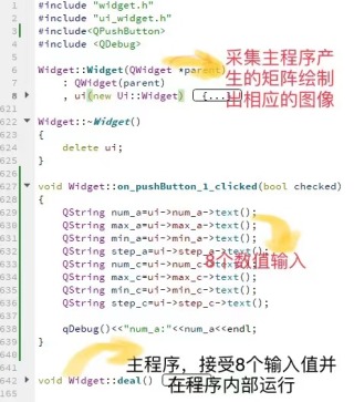
void Widget::on_pushButton_1_clicked(bool checked)
{
    QString num_a=ui->num_a->text();
    QString max_a=ui->max_a->text();
    QString min_a=ui->min_a->text();
    QString step_a=ui->step_a->text();
    QString num_c=ui->num_c->text();
    QString max_c=ui->max_c->text();
    QString min_c=ui->min_c->text();
    QString step_c=ui->step_c->text();

    qDebug()<<"num_a:"<<num_a<<endl;
}


void Widget::deal()
{
    ifstream inFile;
    inFile.open("D:\\MeasureData_sws.data");
    if (!inFile) {
        cerr << "don't able to open file";
        exit(1);
    }
    string s;
    double temdata[200][3] = { {0,0,0} };
    int num = 0;
    int num_row = 0;
    int num_col = 0;
    while (inFile >> s) {
        //data += s;
        //对每次读入的坐标进行处理,去除第一个字符X或Y或Z
        //string tems;
        //int len = s.length();
        //for (int i = 0;i < len-1;i++) {
        //    tems[i] = s[i + 1];
        //}
        s.erase(0, s.find_first_not_of('X'));
        s.erase(0, s.find_first_not_of('Y'));
        s.erase(0, s.find_first_not_of('Z'));
        double temnum = stod(s);
        num_row = num / 3;
        num_col = num % 3;
        temdata[num_row][num_col] = temnum;
        num++;
        //cout.setf(ios::fixed, ios::floatfield);
        //cout << temnum << endl;
    }
    //cout.setf(ios::fixed, ios::floatfield);
    //cout << temdata[199][2] << endl;
    //cout << data[0];
    inFile.close();
    //读取MeasureData_sws.data中的坐标数据
    static mat MeasureData = mat(200, 3, fill::zeros);
    for (int i = 0; i < 200;i++) {
        for (int j = 0; j < 3;j++) {
            MeasureData(i, j) = temdata[i][j];
        }
    }


    //绘制误差图像

    //位置相关误差项辨识计算
    //刀尖点位置误差解算成各轴的几何误差
    //C轴
    mat errorC_pos = mat(6, num_c, fill::zeros);
    mat VARYC = {
        {1, 0 , 0, pointC1(2), -pointC1(1)},
        {0, 1, -pointC1(2), 0, pointC1(0)},
        {0, 0, pointC1(1), -pointC1(0), 0},
        {1, 0, 0, pointC2(2), -pointC2(1)},
        {0, 1, -pointC2(2), 0, pointC2(0)},
        {0, 0, pointC2(1), -pointC2(0), 0}
    };
    mat VARYC_t1t = mat(5, 6, fill::zeros);
    VARYC_t1t = inv(VARYC.t() * VARYC) * VARYC.t();
    for (int i = 0;i < num_c;i++) {
        double C = (min_c + step_c * i) * PI / 180;
        mat rot = {
            {cos(C), -sin(C), 0},
            {sin(C), cos(C), 0},
            {0, 0, 1}
        };
        mat rot_error_C = mat(6, 1, fill::zeros);
        rot_error_C.rows(0, 2) = -rot * (error_C.row(i).cols(0, 2).t());
        rot_error_C.rows(3, 5) = -rot * (error_C.row(i).cols(3, 5).t());
        errorC_pos.rows(0, 4).col(i) = VARYC_t1t * rot_error_C;
        errorC_pos.rows(3, 5).col(i) = errorC_pos.rows(2, 4).col(i);
        errorC_pos(2, i) = 0;
    }
    mat errorC_pos_colzero = mat(errorC_pos.n_rows, 1, fill::zeros);
    errorC_pos.rows(0, errorC_pos.n_rows - 1).col(0) = errorC_pos_colzero;
    //cout << errorC_pos << endl;

    //A轴
    mat errorA_pos = mat(6, num_a, fill::zeros);
    mat VARYA = {
        {0, 0 , 0, pointA1(2) - Paz, -pointA1(1) - Pcy + Pay},
        {1, 0, -pointA1(2) + Paz, 0, pointA1(0) + Pcx},
        {0, 1, pointA1(1) + Pcy - Pay, -pointA1(0) - Pcx, 0},
        {0, 0, 0, pointA2(2) - Paz, -pointA2(1) - Pcy + Pay},
        {1, 0, -pointA2(2) + Paz, 0, pointA2(0) + Pcx},
        {0, 1, pointA2(1) + Pcy - Pay, -pointA2(0) - Pcx, 0}
    };
    mat VARYA_t1t = mat(5, 6, fill::zeros);
    VARYA_t1t = inv(VARYA.t() * VARYA) * VARYA.t();
    for (int i = 0;i < num_a;i++) {
        double A = (min_a + step_a * i) * PI / 180;
        mat rot = {
            {1, 0, 0},
            {0, cos(A), -sin(A)},
            {0, sin(A), cos(A)}
        };
        errorA_pos(0, i) = 0;
        mat rot_error_A = mat(6, 1, fill::zeros);
        rot_error_A.rows(0, 2) = -rot * (error_A.row(i).cols(0, 2).t());
        rot_error_A.rows(3, 5) = -rot * (error_A.row(i).cols(3, 5).t());
        errorA_pos.rows(1, 5).col(i) = VARYA_t1t * rot_error_A;
    }
    //cout << errorA_pos << endl;

    //绘制误差曲线

    //仿真计算
    mat Tp_A = {
        {1, 0, 0, 0},
        {0, 1, 0, Pay},
        {0, 0, 1, Paz},
        {0, 0, 0, 1}
    };
    mat Tp_C = {
        {1, 0, 0, Pcx},
        {0, 1, 0, Pcy - Pay},
        {0, 0, 1, -Paz},
        {0, 0, 0, 1}
    };
    //C轴补偿效果
    mat compensate_C = mat(8, num_c, fill::zeros);
    mat pointC1_wt = mat(4, 1, fill::zeros);
    pointC1_wt.rows(0, 2) = pointC1.t();
    pointC1_wt(3) = 1;
    mat pointC2_wt = mat(4, 1, fill::zeros);
    pointC2_wt.rows(0, 2) = pointC2.t();
    pointC2_wt(3) = 1;
    for (int i = 0;i < num_c;i++) {
        double C = (min_c + step_c * i) * PI / 180;
        //A轴-C轴转换矩阵
        mat Ts_C = {
            {cos(C), sin(C), 0, 0},
            {-sin(C), cos(C), 0, 0},
            {0, 0, 1, 0},
            {0, 0, 0, 1}
        };
        mat Tse_C = {
            {1, -errorC_pos(5,i), errorC_pos(4,i), errorC_pos(0,i)},
            {errorC_pos(5,i), 1, -errorC_pos(3,i), errorC_pos(1,i)},
            {-errorC_pos(4,i), errorC_pos(3,i), 1, errorC_pos(2,i)},
            {0, 0, 0, 1}
        };
        //计算补偿量
        //计算位置1轮廓误差
        compensate_C.rows(0, 3).col(i) = Tp_A * Tp_C * Ts_C * pointC1_wt - Tp_A * Tp_C * Ts_C * Tse_C * pointC1_wt;
        //计算位置2轮廓误差
        compensate_C.rows(4, 7).col(i) = Tp_A * Tp_C * Ts_C * pointC2_wt - Tp_A * Tp_C * Ts_C * Tse_C * pointC2_wt;
    }
    //cout << compensate_C << endl;
    //A轴补偿效果
    mat compensate_A = mat(8, num_a, fill::zeros);
    mat pointA1_wt = mat(4, 1, fill::zeros);
    pointA1_wt.rows(0, 2) = pointA1.t();
    pointA1_wt(3) = 1;
    mat pointA2_wt = mat(4, 1, fill::zeros);
    pointA2_wt.rows(0, 2) = pointA2.t();
    pointA2_wt(3) = 1;
    for (int i = 0;i < num_a;i++) {
        double A = (min_a + step_a * i) * PI / 180;
        //A轴-C轴转换矩阵
        mat Ts_A = {
            {1, 0, 0, 0},
            {0, cos(A), sin(A), 0},
            {0, -sin(A), cos(A), 0},
            {0, 0, 0, 1}
        };
        mat Tse_A = {
            {1, -errorA_pos(5,i), errorA_pos(4,i), errorA_pos(0,i)},
            {errorA_pos(5,i), 1, -errorA_pos(3,i), errorA_pos(1,i)},
            {-errorA_pos(4,i), errorA_pos(3,i), 1, errorA_pos(2,i)},
            {0, 0, 0, 1}
        };
        //计算补偿量
        //计算位置1轮廓误差
        compensate_A.rows(0, 3).col(i) = Tp_A * Ts_A * Tp_C * pointA1_wt - Tp_A * Ts_A * Tse_A * Tp_C * pointA1_wt;
        //计算位置2轮廓误差
        compensate_A.rows(4, 7).col(i) = Tp_A * Ts_A * Tp_C * pointA2_wt - Tp_A * Ts_A * Tse_A * Tp_C * pointA2_wt;
    }
    cout << compensate_A << endl;
    qDebug("waiting");
}


