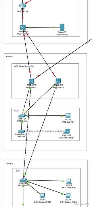
下面那部分的stp和vlan已经划分好了,两个3650交换机怎么连通到最上面的3650

 分享
分享
 关注
关注引自免费微信小程序:皆我百晓生
为了实现这个网络拓扑的连通性,你需要按照以下步骤配置两台3650交换机(假设它们分别是SWITCH1和SWITCH2)与上一级3650交换机(SERVER-PT)的连接,并确保VLAN和STP配置正确。这里假设所有交换机都运行在相同版本的Cisco IOS软件上。
首先,我们需要对交换机进行基本配置,包括接口描述、VLAN创建以及STP的全局开启。以下是配置示例:
服务器端3650交换机 SERVER-PT 配置
configure terminal
interface FastEthernet 0/1
description Connection to SWITCH1
switchport mode trunk
spanning-tree portfast
exit
interface FastEthernet 0/2
description Connection to SWITCH2
switchport mode trunk
spanning-tree portfast
exit
spanning-tree mode mst
spanning-tree vlan 10,20,30,40 priority 4096
spanning-tree root primary
spanning-tree mst configuration
instance 0 vlan 10,20
instance 1 vlan 30,40
end
SWITCH1 和 SWITCH2 的配置
对于SWITCH1和SWITCH2,配置会类似,但需要根据实际物理连接调整端口。例如,假定SWITCH1通过FastEthernet 0/1连接到SERVER-PT,而SWITCH2通过FastEthernet 0/2连接,则配置如下:
configure terminal
interface FastEthernet 0/1
description Connection to SERVER-PT
switchport mode trunk
switchport trunk allowed vlan add 10,20,30,40
spanning-tree portfast
exit
interface FastEthernet 0/2
description Connection to Block A Switch1 or Block B Switch
switchport mode access
switchport access vlan 10
exit
interface FastEthernet 0/3
description Connection to Block A Switch2 or Block B Switch
switchport mode access
switchport access vlan 20
exit
interface FastEthernet 0/4
description Connection to Block A Switch2 or Block B Switch
switchport mode access
switchport access vlan 30
exit
interface FastEthernet 0/5
description Connection to Block A Switch2 or Block B Switch
switchport mode access
switchport access vlan 40
exit
spanning-tree mode mst
spanning-tree vlan 10,20,30,40 priority 8192
spanning-tree root secondary
spanning-tree mst configuration
instance 0 vlan 10,20
instance 1 vlan 30,40
end
注意:这里的配置是基于VLAN 10、20、30、40分别用于不同的区域。请根据实际需求调整VLAN分配。另外,交换机之间的物理连接需要按照实际情况进行调整。
完成上述配置后,你应该可以在SERVER-PT、SWITCH1和SWITCH2之间建立一个多实例生成树(MSTP),并确保各个VLAN在网络中的通信畅通。如果遇到任何问题,可以检查交换机的日志或使用show spanning-tree命令查看STP状态。如果你需要画图,由于文本环境限制,我建议你使用在线绘图工具,如Visio或Draw.io,根据提供的信息绘制出相应的网络拓扑图。
分享 创建了问题
5月27日
创建了问题
5月27日
