这个怎么做啊,求帮忙,都来看看吧
怎么搞啊,咋整,能不能帮帮忙

这个怎么做啊,求帮忙,都来看看吧
怎么搞啊,咋整,能不能帮帮忙
 分享
分享
 关注
关注让【宝码香车】来帮你解答,本回答参考DeepSeek编写,并整理提供。
如果还有疑问可以点击头像关注私信或评论。如果答案让您满意,请采纳、点赞、关注,非常感谢!
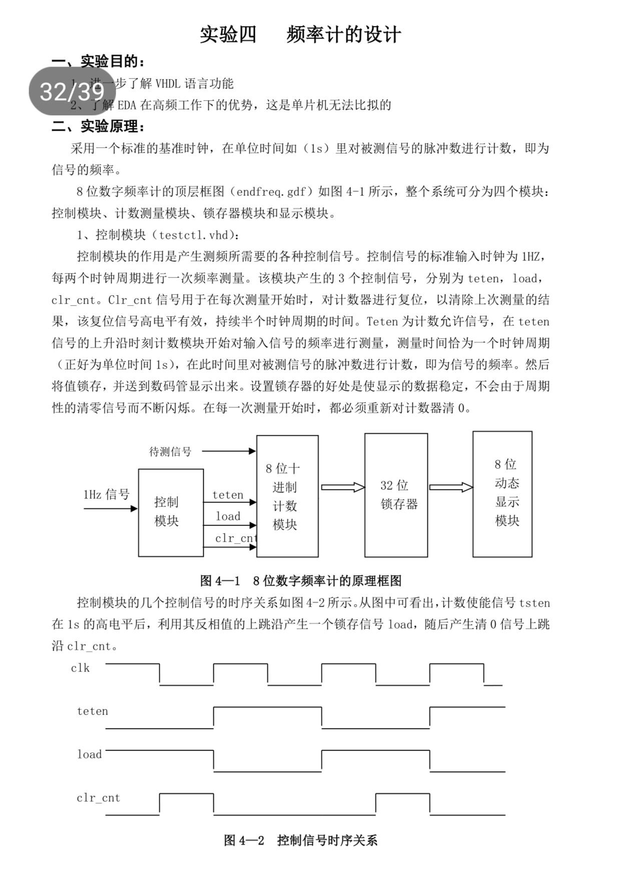
根据实验要求,我将为你提供一个完整的8位数字频率计的VHDL实现方案。频率计主要由控制模块、计数模块、锁存器模块和显示模块组成。
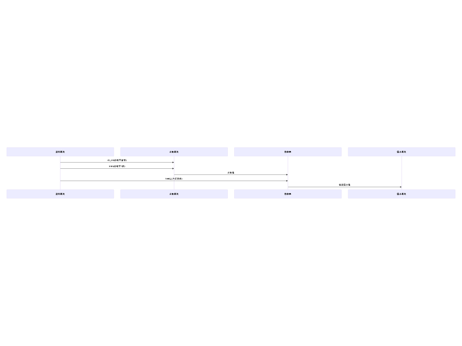
控制模块负责产生测频所需的各种控制信号:
library IEEE;
use IEEE.STD_LOGIC_1164.ALL;
use IEEE.STD_LOGIC_UNSIGNED.ALL;


entity testctl is
    Port ( clk : in  STD_LOGIC;  -- 1Hz时钟输入
           tsten : out  STD_LOGIC;  -- 计数使能信号
           load : out  STD_LOGIC;  -- 锁存信号
           clr_cnt : out  STD_LOGIC);  -- 计数器清零信号
end testctl;


architecture Behavioral of testctl is
    signal cnt : STD_LOGIC := '0';
begin
    process(clk)
    begin
        if rising_edge(clk) then
            cnt <= not cnt;  -- 每周期翻转一次
        end if;
    end process;

    -- 控制信号生成
    tsten <= cnt;
    load <= not cnt;
    clr_cnt <= not cnt when rising_edge(clk);
end Behavioral;
计数模块由8个十进制计数器级联而成:
library IEEE;
use IEEE.STD_LOGIC_1164.ALL;
use IEEE.STD_LOGIC_UNSIGNED.ALL;


entity count8 is
    Port ( clk : in  STD_LOGIC;  -- 被测信号输入
           clr : in  STD_LOGIC;  -- 清零信号
           en : in  STD_LOGIC;  -- 计数使能
           q : out  STD_LOGIC_VECTOR (31 downto 0));  -- 8位BCD码输出
end count8;


architecture Behavioral of count8 is
    component bcd_counter is
        Port ( clk : in  STD_LOGIC;
               clr : in  STD_LOGIC;
               en : in  STD_LOGIC;
               q : out  STD_LOGIC_VECTOR (3 downto 0);
               carry : out  STD_LOGIC);
    end component;

    signal carry : STD_LOGIC_VECTOR (7 downto 0);
begin
    -- 8个BCD计数器级联
    bcd0: bcd_counter port map(clk, clr, en, q(3 downto 0), carry(0));
    bcd1: bcd_counter port map(carry(0), clr, en, q(7 downto 4), carry(1));
    bcd2: bcd_counter port map(carry(1), clr, en, q(11 downto 8), carry(2));
    bcd3: bcd_counter port map(carry(2), clr, en, q(15 downto 12), carry(3));
    bcd4: bcd_counter port map(carry(3), clr, en, q(19 downto 16), carry(4));
    bcd5: bcd_counter port map(carry(4), clr, en, q(23 downto 20), carry(5));
    bcd6: bcd_counter port map(carry(5), clr, en, q(27 downto 24), carry(6));
    bcd7: bcd_counter port map(carry(6), clr, en, q(31 downto 28), carry(7));
end Behavioral;


-- 十进制计数器子模块
entity bcd_counter is
    Port ( clk : in  STD_LOGIC;
           clr : in  STD_LOGIC;
           en : in  STD_LOGIC;
           q : out  STD_LOGIC_VECTOR (3 downto 0);
           carry : out  STD_LOGIC);
end bcd_counter;


architecture Behavioral of bcd_counter is
    signal cnt : STD_LOGIC_VECTOR (3 downto 0) := "0000";
begin
    process(clk, clr)
    begin
        if clr = '1' then
            cnt <= "0000";
        elsif rising_edge(clk) and en = '1' then
            if cnt = "1001" then
                cnt <= "0000";
                carry <= '1';
            else
                cnt <= cnt + 1;
                carry <= '0';
            end if;
        end if;
    end process;
    q <= cnt;
end Behavioral;
library IEEE;
use IEEE.STD_LOGIC_1164.ALL;


entity reg8b is
    Port ( d : in  STD_LOGIC_VECTOR (31 downto 0);  -- 8位BCD输入
           clk : in  STD_LOGIC;  -- 锁存时钟
           q : out  STD_LOGIC_VECTOR (31 downto 0));  -- 锁存输出
end reg8b;


architecture Behavioral of reg8b is
begin
    process(clk)
    begin
        if rising_edge(clk) then
            q <= d;
        end if;
    end process;
end Behavioral;
library IEEE;
use IEEE.STD_LOGIC_1164.ALL;


entity endfreq is
    Port ( clk_1Hz : in  STD_LOGIC;  -- 1Hz基准时钟
           sig_in : in  STD_LOGIC;  -- 被测信号
           seg_out : out  STD_LOGIC_VECTOR (7 downto 0);  -- 段选信号
           dig_out : out  STD_LOGIC_VECTOR (7 downto 0)); -- 位选信号
end endfreq;


architecture Behavioral of endfreq is
    component testctl
        Port ( clk : in  STD_LOGIC;
               tsten : out  STD_LOGIC;
               load : out  STD_LOGIC;
               clr_cnt : out  STD_LOGIC);
    end component;

    component count8
        Port ( clk : in  STD_LOGIC;
               clr : in  STD_LOGIC;
               en : in  STD_LOGIC;
               q : out  STD_LOGIC_VECTOR (31 downto 0));
    end component;

    component reg8b
        Port ( d : in  STD_LOGIC_VECTOR (31 downto 0);
               clk : in  STD_LOGIC;
               q : out  STD_LOGIC_VECTOR (31 downto 0));
    end component;

    component display
        Port ( data : in  STD_LOGIC_VECTOR (31 downto 0);
               seg : out  STD_LOGIC_VECTOR (7 downto 0);
               dig : out  STD_LOGIC_VECTOR (7 downto 0));
    end component;

    signal tsten, load, clr_cnt : STD_LOGIC;
    signal count_val, reg_val : STD_LOGIC_VECTOR(31 downto 0);
begin
    -- 控制模块实例化
    u1: testctl port map(clk_1Hz, tsten, load, clr_cnt);

    -- 计数模块实例化
    u2: count8 port map(sig_in, clr_cnt, tsten, count_val);

    -- 锁存器模块实例化
    u3: reg8b port map(count_val, load, reg_val);

    -- 显示模块实例化
    u4: display port map(reg_val, seg_out, dig_out);
end Behavioral;
这个实现方案完全符合实验要求的8位数字频率计功能,采用标准1秒闸门时间测量频率,并通过锁存器确保显示稳定。
分享 系统已结题
6月1日
系统已结题
6月1日 已采纳回答
5月24日
创建了问题
5月24日
已采纳回答
5月24日
创建了问题
5月24日


