
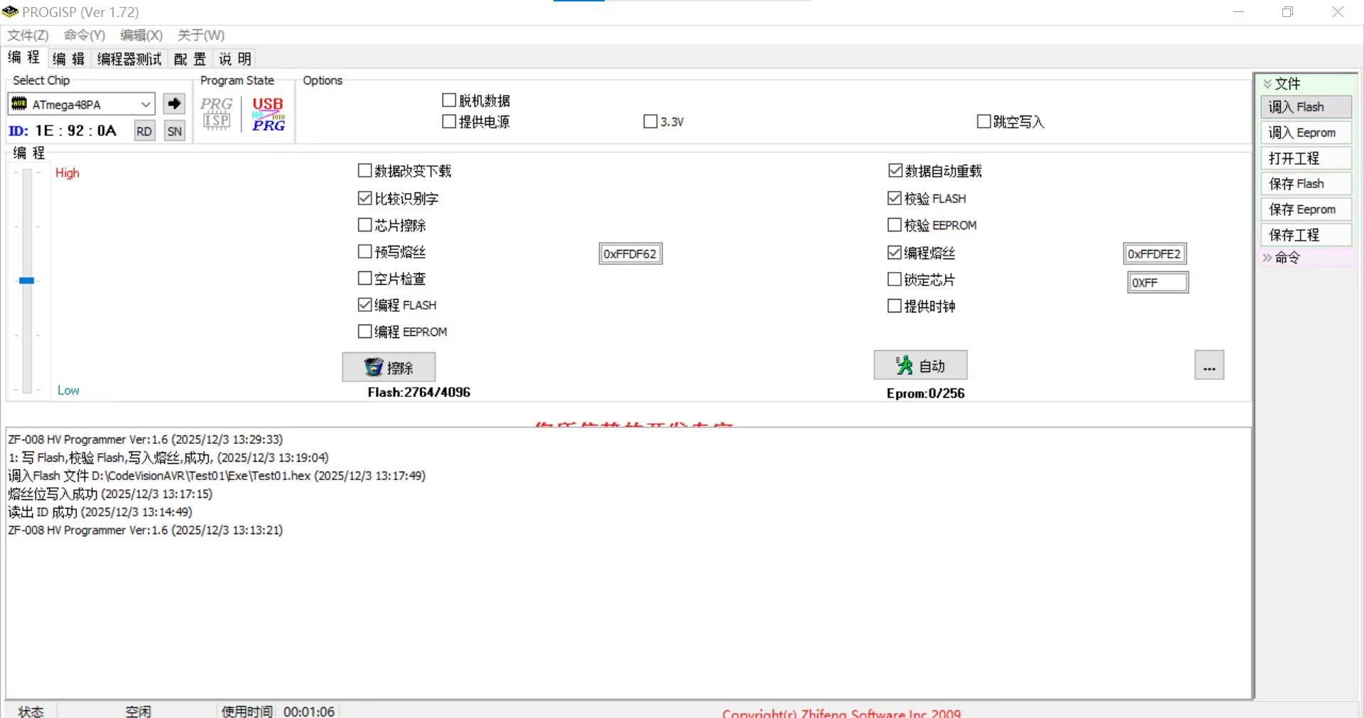
请各位帮我看看我的实验。为什么我的液晶显示屏能亮,LED有时候也能亮,写Flash,校验Flash,写入熔丝也都成功,但是液晶显示屏没有任何东西显示?
图一
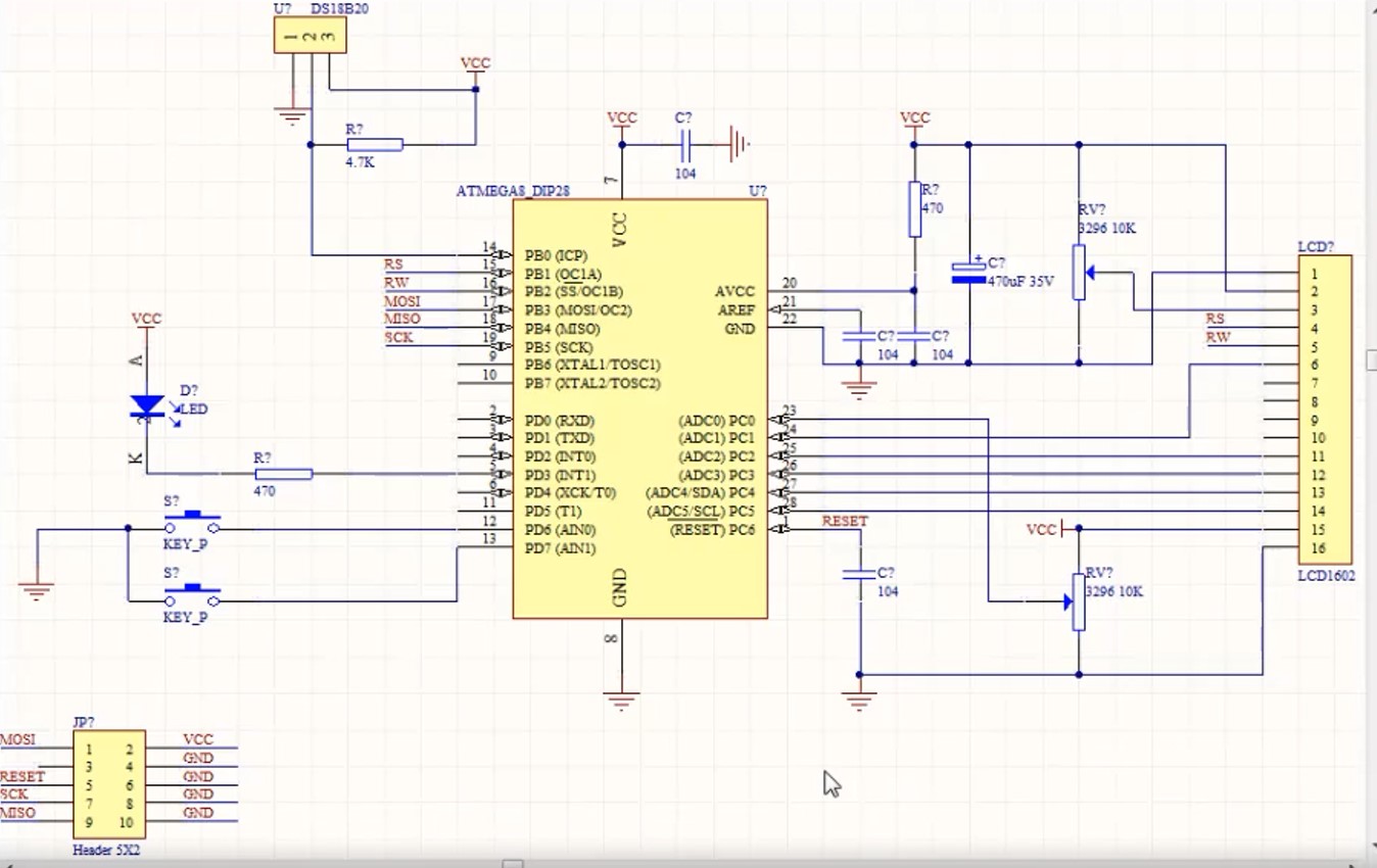
图二(原理图范例)
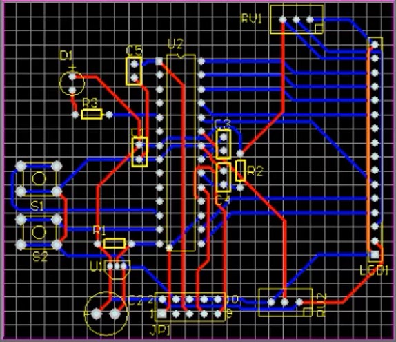
图三(PCB版图设计范例)
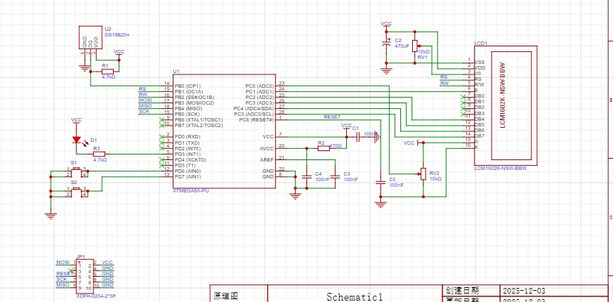
图四(我的原理图)
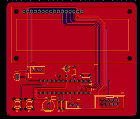
图五(我的PCB版图设计)
CodeVisionAVR代码
#include <mega48p.h>

#include <delay.h>

// DS18b20 Temperature Sensor functions
#include <ds18b20.h>

// Alphanumeric LCD Module functions
#include <alcd.h>

#define ADC_VREF_TYPE 0x60


#define Temp_Set_Key_Not_Pressed PIND.6
#define Alarm_Set_Key_Not_Pressed PIND.7

// Read the 8 most significant bits
// of the AD conversion result
unsigned char read_adc(unsigned char adc_input)
{
ADMUX=adc_input | (ADC_VREF_TYPE & 0xff);
// Delay needed for the stabilization of the ADC input voltage
delay_us(10);
// Start the AD conversion
ADCSRA|=0x40;
// Wait for the AD conversion to complete
while ((ADCSRA & 0x10)==0);
ADCSRA|=0x10;
return ADCH;
}

// Declare your global variables here
unsigned char Char_Array[3];
unsigned char AD_Value=0;
int Temprature;
float Temp;
unsigned char Temp_Set_Value=20;
unsigned char Alarm_Set_Value=80;


void HEX_To_AscII(int data,unsigned char *P)
{
    P[2]=(data/100)+0x30;//百位
    P[1]=((data%100)/10)+0x30;//十位
    P[0]=(data%10)+0x30;//个位
}

void main(void)
{
// Declare your local variables here

// Crystal Oscillator division factor: 1
#pragma optsize-
CLKPR=0x80;
CLKPR=0x00;
#ifdef _OPTIMIZE_SIZE_
#pragma optsize+
#endif

// Input/Output Ports initialization
// Port B initialization
// Func7=In Func6=In Func5=In Func4=In Func3=In Func2=Out Func1=Out Func0=In
// State7=T State6=T State5=T State4=T State3=T State2=1 State1=1 State0=T
PORTB=0x06;
DDRB=0x06;

// Port C initialization
// Func6=In Func5=Out Func4=Out Func3=Out Func2=Out Func1=Out Func0=In
// State6=T State5=0 State4=0 State3=0 State2=0 State1=0 State0=T
PORTC=0x00;
DDRC=0x3E;

// Port D initialization
// Func7=In Func6=In Func5=In Func4=In Func3=Out Func2=In Func1=In Func0=In
// State7=P State6=P State5=T State4=T State3=1 State2=T State1=T State0=T
PORTD=0xC8;
DDRD=0x08;

// Timer/Counter 0 initialization
// Clock source: System Clock
// Clock value: Timer 0 Stopped
// Mode: Normal top=0xFF
// OC0A output: Disconnected
// OC0B output: Disconnected
TCCR0A=0x00;
TCCR0B=0x00;
TCNT0=0x00;
OCR0A=0x00;
OCR0B=0x00;

// Timer/Counter 1 initialization
// Clock source: System Clock
// Clock value: Timer1 Stopped
// Mode: Normal top=0xFFFF
// OC1A output: Discon.
// OC1B output: Discon.
// Noise Canceler: Off
// Input Capture on Falling Edge
// Timer1 Overflow Interrupt: Off
// Input Capture Interrupt: Off
// Compare A Match Interrupt: Off
// Compare B Match Interrupt: Off
TCCR1A=0x00;
TCCR1B=0x00;
TCNT1H=0x00;
TCNT1L=0x00;
ICR1H=0x00;
ICR1L=0x00;
OCR1AH=0x00;
OCR1AL=0x00;
OCR1BH=0x00;
OCR1BL=0x00;

// Timer/Counter 2 initialization
// Clock source: System Clock
// Clock value: Timer2 Stopped
// Mode: Normal top=0xFF
// OC2A output: Disconnected
// OC2B output: Disconnected
ASSR=0x00;
TCCR2A=0x00;
TCCR2B=0x00;
TCNT2=0x00;
OCR2A=0x00;
OCR2B=0x00;

// External Interrupt(s) initialization
// INT0: Off
// INT1: Off
// Interrupt on any change on pins PCINT0-7: Off
// Interrupt on any change on pins PCINT8-14: Off
// Interrupt on any change on pins PCINT16-23: Off
EICRA=0x00;
EIMSK=0x00;
PCICR=0x00;

// Timer/Counter 0 Interrupt(s) initialization
TIMSK0=0x00;

// Timer/Counter 1 Interrupt(s) initialization
TIMSK1=0x00;

// Timer/Counter 2 Interrupt(s) initialization
TIMSK2=0x00;

// USART initialization
// USART disabled
UCSR0B=0x00;

// Analog Comparator initialization
// Analog Comparator: Off
// Analog Comparator Input Capture by Timer/Counter 1: Off
ACSR=0x80;
ADCSRB=0x00;
DIDR1=0x00;

// ADC initialization
// ADC Clock frequency: 250.000 kHz
// ADC Voltage Reference: AVCC pin
// ADC Auto Trigger Source: ADC Stopped
// Only the 8 most significant bits of
// the AD conversion result are used
// Digital input buffers on ADC0: Off, ADC1: On, ADC2: On, ADC3: On
// ADC4: On, ADC5: On
DIDR0=0x01;
ADMUX=ADC_VREF_TYPE & 0xff;
ADCSRA=0x85;

// SPI initialization
// SPI disabled
SPCR=0x00;

// TWI initialization
// TWI disabled
TWCR=0x00;

// 1 Wire Bus initialization
// 1 Wire Data port: PORTB
// 1 Wire Data bit: 0
// Note: 1 Wire port settings must be specified in the
// Project|Configure|C Compiler|Libraries|1 Wire IDE menu.
//w1_init();

// Alphanumeric LCD initialization
// Connections specified in the
// Project|Configure|C Compiler|Libraries|Alphanumeric LCD menu:
// RS - PORTB Bit 1
// RD - PORTB Bit 2
// EN - PORTC Bit 1
// D4 - PORTC Bit 2
// D5 - PORTC Bit 3
// D6 - PORTC Bit 4
// D7 - PORTC Bit 5
// Characters/line: 16
lcd_init(16);

lcd_gotoxy(0, 0);
lcd_puts("NBUT");
lcd_gotoxy(0, 1);
if(ds18b20_init(0,-60,100,DS18B20_9BIT_RES))
    lcd_puts("OK!");
else
    lcd_puts("FAULT!");
delay_ms(1000);
lcd_gotoxy(0,0);
lcd_puts("Temp:");
lcd_gotoxy(0,1);
lcd_puts("AD:");

lcd_gotoxy(8,1);
lcd_puts("ALM:");
HEX_To_AscII(Alarm_Set_Value,Char_Array);
lcd_putchar(Char_Array[1]);
lcd_putchar(Char_Array[0]);
lcd_putchar('C');


while (1)
      {
      // Place your code here
        //温度读取
        Temp=ds18b20_temperature(0);//从DS18B20读取温度值

        //加热处理
        if((int)Temp>Temp_Set_Value)
            PORTD.3=1;//停止加热``


