这幅图该怎么理解和设计电路,脉冲发生器和计数译码显示器,可以分开设计为什么,可以设计再一起吗

 分享
分享
晚上好🌙🌙🌙
本答案参考通义千问
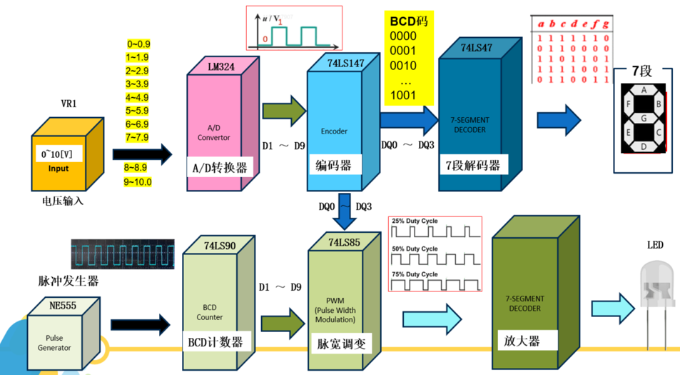
你提到的“脉冲发生器、计数器、译码显示器”是数字电路中常见的模块,通常用于时序控制、状态显示、信号生成等应用场景。以下是对这幅图的分析和设计思路,包括分开设计与整合设计的优缺点及实现方式。
// Verilog代码示例:555定时器替代的简单脉冲发生器
module pulse_generator(
    input clk,
    output reg pulse
);

    reg [3:0] count;
    always @(posedge clk) begin
        count <= count + 1;
        if (count == 4) begin
            pulse <= 1;
            count <= 0;
        end else begin
            pulse <= 0;
        end
    end
endmodule
// Verilog代码示例:4位二进制计数器
module counter(
    input clk,
    input rst,
    output reg [3:0] count
);

    always @(posedge clk or posedge rst) begin
        if (rst)
            count <= 0;
        else
            count <= count + 1;
    end
endmodule
// 7段数码管译码器(BCD -> 7段)
module seven_segment_decoder(
    input [3:0] bcd,
    output reg [6:0] seg
);

    always @(*) begin
        case (bcd)
            4'b0000: seg = 7'b1000000; // 0
            4'b0001: seg = 7'b1111001; // 1
            4'b0010: seg = 7'b0100100; // 2
            4'b0011: seg = 7'b0110000; // 3
            4'b0100: seg = 7'b0011001; // 4
            4'b0101: seg = 7'b0010010; // 5
            4'b0110: seg = 7'b0000010; // 6
            4'b0111: seg = 7'b1111000; // 7
            4'b1000: seg = 7'b0000000; // 8
            4'b1001: seg = 7'b0010000; // 9
            default: seg = 7'b1111111; // 空白
        endcase
    end
endmodule
module top_module(
    input clk,
    input rst,
    output [6:0] seg_out
);

    wire pulse;
    wire [3:0] count;

    pulse_generator u1(.clk(clk), .pulse(pulse));
    counter u2(.clk(pulse), .rst(rst), .count(count));
    seven_segment_decoder u3(.bcd(count), .seg(seg_out));

endmodule
module integrated_design(
    input clk,
    input rst,
    output [6:0] seg_out
);

    reg [3:0] count;
    reg pulse;
    reg [3:0] bcd;

    always @(posedge clk or posedge rst) begin
        if (rst) begin
            count <= 0;
            pulse <= 0;
        end else begin
            count <= count + 1;
            pulse <= (count == 4) ? 1 : 0;
        end
    end

    // 译码逻辑直接写在主模块中
    always @(*) begin
        case (count)
            4'b0000: seg_out = 7'b1000000;
            4'b0001: seg_out = 7'b1111001;
            ...
            default: seg_out = 7'b1111111;
        endcase
    end

endmodule
| 项目 | 分开设计 | 整合设计 | |------|-----------|-----------| | 调试难度 | 低 | 高 | | 复用性 | 强 | 弱 | | 逻辑清晰度 | 高 | 低 | | 嵌入式/PCB需求 | 适用 | 适用 |
如有具体电路图或设计需求,欢迎提供,我可以进一步帮你分析和优化。
分享 创建了问题
4月1日
创建了问题
4月1日


