设计要求:该数字系统完成对十字路口交通信号灯的控制,十字路口由一条东西方向的主干道(简称A道)和南北方向的支干道(简称B道)构成。十字路口交通灯控制规则为:
(1) 初始状态为4个方向的红灯全亮,时间1s。
(2) 东西方向绿灯亮,南北方向红灯亮。东西方向通车,时间35s。
(3) 东西方向黄灯亮,南北方向红灯亮,时间5s。
(4) 东西方向红灯亮,南北方向绿灯亮。南北方向通车,时间50s。
(5) 东西方向红灯亮,南,北方向黄灯亮,时间5s。
(6) 返回(2),继续运行。
(7) 如果发生紧急事件,例如救护车,警车通过,则按下单脉冲按钮,使得东,南,西,北四个方向红灯亮。紧急事件结束后,松开单脉冲按钮,将恢复到被打断的状态继续运行。
任务:主要通过Verilog语言并仿真实现设计功能,用数码管显示剩余时间。
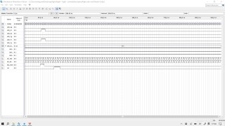
目前按键功能可以正常产生波形,但是红黄绿灯无法正常产生。
//状态机模块
module light(
  input clk_50MHz,
  input clk_1Hz,
  input rst,
  input key_SOS,//紧急按钮,按下后启动紧急模式
  output reg LED_Xr,//南北方向红灯
  output reg LED_Xy,//南北方向黄灯
  output reg LED_Xg,//南北方向绿灯
  output reg LED_Yr,//东西方向红灯
  output reg LED_Yy,//东西方向黄灯
  output reg LED_Yg,//东西方向绿灯
  output reg [7:0] CntDis,//[7:4]为数码管高位,[3:0]为数码管低位
  output wire [2:0] LED_state//状态指示灯
    );
    reg [2:0] state;
    reg [5:0] cnt_96;//96进制计数器

    assign LED_state=state;
    initial state=0;


    parameter S0=3'b000;//s0:全红1s
    parameter S1=3'b001;//S1:南北方向红灯亮,东西方向绿灯亮35s
    parameter S2=3'b010;//S2:南北方向红灯亮,东西方向黄灯亮5s
    parameter S3=3'b011;//S3:南北方向绿灯亮,东西方向红灯亮50s
    parameter S4=3'b100;//S4:南北方向黄灯亮,东西方向红灯亮5s
    parameter s5=3'b101;//s5:返回s1
    parameter S6=3'b111;//S4:全红(紧急模式)
    always@(posedge clk_1Hz )//or negedge rst
    begin
      if(!rst)
        cnt_96<=0;
      //else
        begin
          if(cnt_96>=96)
            cnt_96<=0;
          //else
            cnt_96<=cnt_96+1;
        end
          //数码管显示
    begin
        if(cnt_96>=90)
         begin
          CntDis[7:4]<=9;
          CntDis[3:0]<=cnt_96-90;
         end
     begin
        if(cnt_96>=80)
         begin
          CntDis[7:4]<=8;
          CntDis[3:0]<=cnt_96-80;
         end
     begin
        if(cnt_96>=70)
         begin
          CntDis[7:4]<=7;
          CntDis[3:0]<=cnt_96-70;
         end
     begin
        if(cnt_96>=60)
         begin
          CntDis[7:4]<=6;
          CntDis[3:0]<=cnt_96-60;
         end
     begin
        if(cnt_96>=50)
         begin
           CntDis[7:4]<=5;
           CntDis[3:0]<=cnt_96-50;
          end
     begin
        if(cnt_96>=40)
         begin
           CntDis[7:4]<=4;
           CntDis[3:0]<=cnt_96-40;
         end
     begin
        if(cnt_96>=30)
         begin
           CntDis[7:4]<=3;
           CntDis[3:0]<=cnt_96-30;
         end
     begin
         if(cnt_96>=20)
             begin
                CntDis[7:4]<=2;
                CntDis[3:0]<=cnt_96-20;
          end
      begin
        if(cnt_96>=10)
           begin
             CntDis[7:4]<=1;
             CntDis[3:0]<=cnt_96-10;
           end
        begin
        if(cnt_96>=0)
           begin
             CntDis[7:4]<=0;
             CntDis[3:0]<=cnt_96;
           end
       end
       end
         end
         end
         end
         end
         end
         end
         end
         end


    begin
      if(!rst)//
        begin
          LED_Xr<=0;
          LED_Xy<=0;
          LED_Xg<=0;
          LED_Yr<=0;
          LED_Yy<=0;
          LED_Yg<=0;
        end
      //else
        begin
          if(key_SOS)
            begin
             LED_Xr<=1;
             LED_Xy<=0;
             LED_Xg<=0;
             LED_Yr<=1;
             LED_Yy<=0;
             LED_Yg<=0;
             cnt_96<=0;
             CntDis[7:4]<=0;
             CntDis[3:0]<=0;
             state<=3'b111;
            end
          else
            begin
              case(state)
              S0:
                begin
                  if(cnt_96<=1)
                    begin
                    LED_Xr<=1;
                    LED_Xy<=0;
                    LED_Xg<=0;
                    LED_Yr<=1;
                    LED_Yy<=0;
                    LED_Yg<=0;
                    end
                  else
                    state<=S1;
               end
                  S1:
                begin
                  if(cnt_96<=36)
                    begin
                    LED_Xr<=1;
                    LED_Xy<=0;
                    LED_Xg<=0;
                    LED_Yr<=0;
                    LED_Yy<=0;
                    LED_Yg<=1;
                    end
                  else
                    state<=S2;
                end
              S2:
                begin
                  if(cnt_96<=41)
                    begin
                    LED_Xr<=1;
                    LED_Xy<=0;
                    LED_Xg<=0;
                    LED_Yr<=0;
                    LED_Yy<=1;
                    LED_Yg<=0;
                    end
                 else
                  state<=S3;
              end
              S3:
                begin
                  if(cnt_96<=91)
                    begin
                    LED_Xr<=0;
                    LED_Xy<=0;
                    LED_Xg<=1;
                    LED_Yr<=1;
                    LED_Yy<=0;
                    LED_Yg<=0;
                    end
                  else
                    state<=S4;
                end
              S4:
                begin
                     if(cnt_96<=96)
                    begin
                    LED_Xr<=0;
                    LED_Xy<=1;
                    LED_Xg<=0;
                    LED_Yr<=1;
                    LED_Yy<=0;
                    LED_Yg<=0;
                    end
                  else
                    state<=S1;
                      end

              endcase
             end
             end
         end
     end

endmodule
/*译码器模块*/
module v_decoder(
        input clk_50MHz,
        input rst,
        input [3:0] IN_CODE,
        output reg [6:0] OUT_CODE
        );
    always@(posedge clk_50MHz or negedge rst)
  begin
        if(!rst)
            begin
            OUT_CODE<=0;
            end
        else
            begin
            case(IN_CODE)
                    0:OUT_CODE<=7'b1111110;
                    1:OUT_CODE<=7'b0110000;
                    2:OUT_CODE<=7'b1101001;
                    3:OUT_CODE<=7'b1111001;
                    4:OUT_CODE<=7'b0110011;
                    5:OUT_CODE<=7'b1011011;
                    6:OUT_CODE<=7'b1011111;
                    7:OUT_CODE<=7'b1110000;
                    8:OUT_CODE<=7'b1111111;
                    9:OUT_CODE<=7'b1110011;
                    default:OUT_CODE<=7'b0000000;
            endcase
            end
    end
endmodule
/*分频模块*/
module v_div(
    input clk_50MHz,
    input rst,
    output reg clk_1Hz
    );
    reg [24:0] cnt;//计数器
    initial
    begin
      clk_1Hz<=0;
      cnt<=0;
    end
    always @(posedge clk_50MHz or negedge rst)
    begin
      if(!rst)
        begin
          clk_1Hz<=0;
          cnt<=0;
        end
      else if(cnt==24999999)
        begin
          clk_1Hz<=~clk_1Hz;
          cnt<=0;
        end
      else
        cnt<=cnt+1;
    end
endmodule
我做的仿真波形如下: