
如图所示,对整体tb仿真时会出现高阻态的蓝色Z
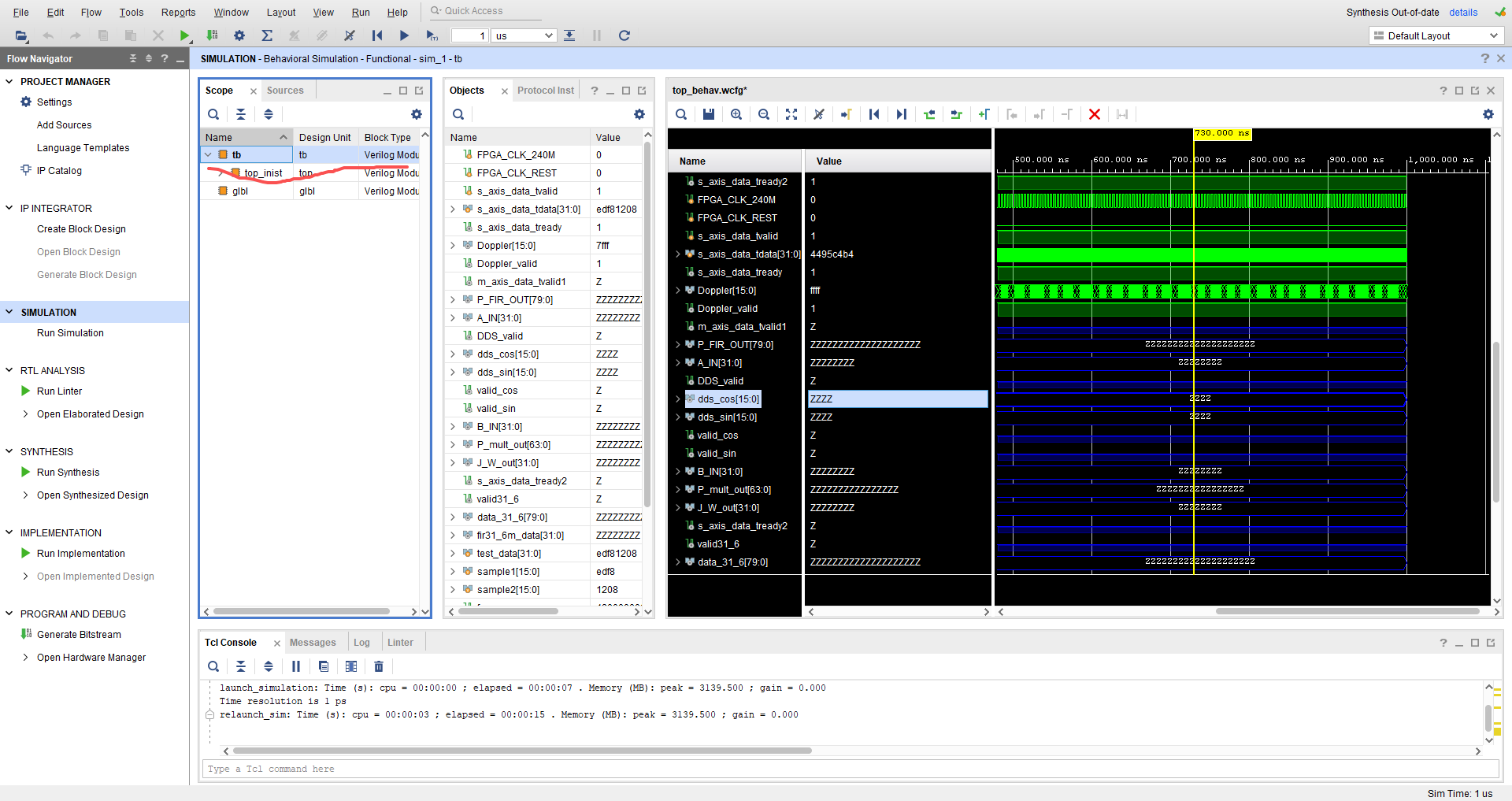
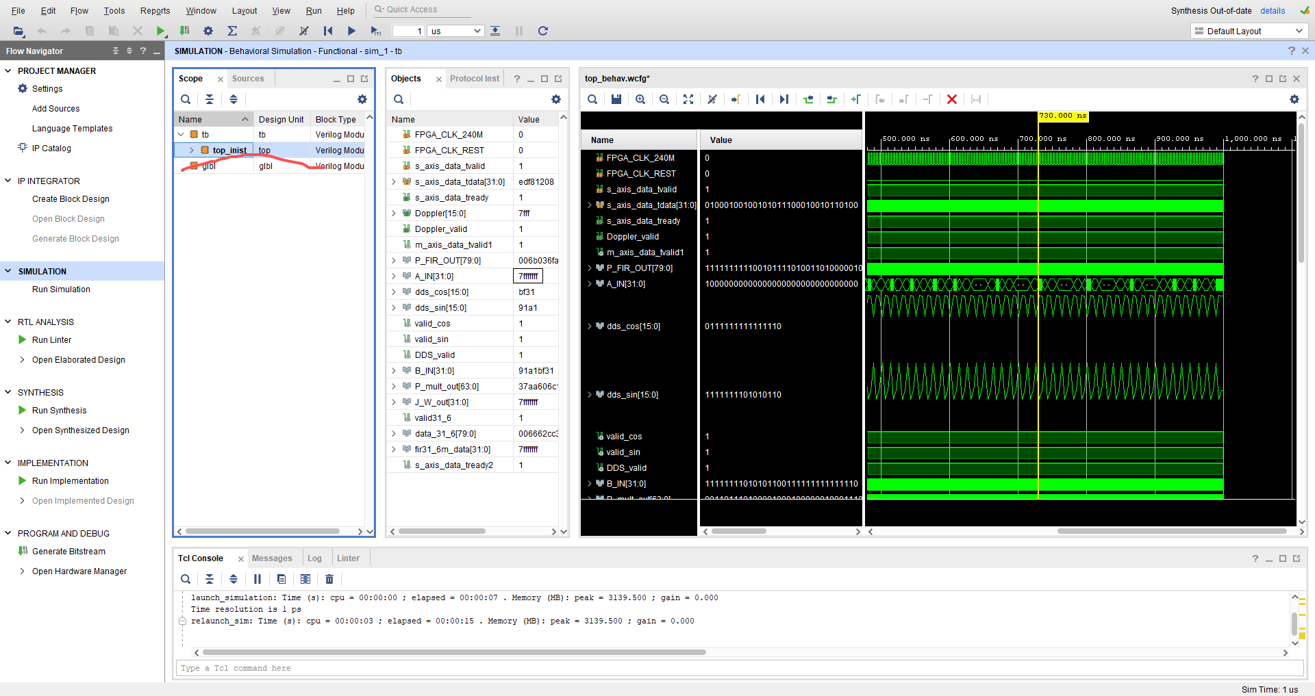
但是若切换到单独对实例化的top仿真则波形正常且其余模块也正常
没遇到过这种问题,求了解的人解答

如图所示,对整体tb仿真时会出现高阻态的蓝色Z
 分享
分享
 关注
关注让 “紫雾凌寒” 来帮你回答,本回答结合 DeepSeek
如果还有问题,请评论或点击头像私信,如果有帮助到您, 请关注、采纳、点赞
module top_module (
    input wire clk,
    input wire rst,
    output wire [7:0] data_out
);
    // 实例化子模块
    sub_module u1 (
       .clk(clk),
       .rst(rst),
       .data_out(data_out)
    );
endmodule

module sub_module (
    input wire clk,
    input wire rst,
    output reg [7:0] data_out
);
    always @(posedge clk or posedge rst) begin
        if (rst) begin
            data_out <= 8'b0;
        end else begin
            data_out <= data_out + 1;
        end
    end
endmodule
- 在tb中检查连接时,要确保每个信号都连接到了正确的位置,没有悬空或者连接错误的情况。
module tb_top_module;
    reg clk;
    reg rst;
    wire [7:0] data_out;

    top_module uut (
       .clk(clk),
       .rst(rst),
       .data_out(data_out)
    );

    initial begin
        clk = 0;
        forever #5 clk = ~clk; // 10ns周期的时钟
    end

    initial begin
        rst = 1;
        #20;
        rst = 0;
    end
endmodule
- 确保激励信号能够正确地触发模块的功能,并且不会导致信号处于不确定状态。
希望以上解答对您有所帮助。如果您有任何疑问,欢迎在评论区提出。
分享 系统已结题
12月18日
系统已结题
12月18日 已采纳回答
12月10日
创建了问题
12月10日
已采纳回答
12月10日
创建了问题
12月10日


